Hot Rod Forum banner

General assembly questions

8.3K views 53 replies 9 participants last post by  BogiesAnnex1  
#1 ·
I realized I'm going to be asking for some advice here on various topics and I'm hoping I can just put them all in one place.

For starters:

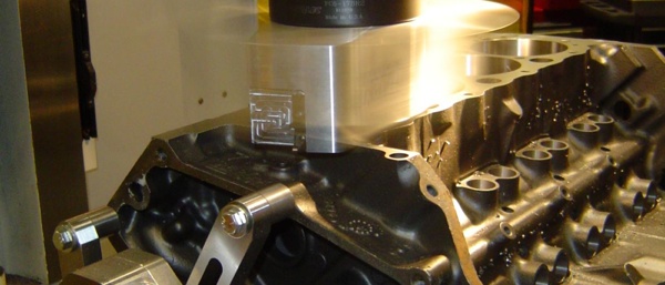
We are getting ready to install the crankshaft and piston assemblies. We did not balance the engine. We did not weigh the small ends and big ends separately, and we did not pay the machine shop to balance the crank. This is a 6,000 rpm max street motor. No sanctified racing is expected. Short blasts to 6000 rpm where we expect the camshaft to peak is it.

With that said:
We have weighed the piston and rod assemblies. we have a maximum spread of 9.1 grams. If i put the rods back in order, i have assembly pairs that are 7.8, 1.4, 2, and 0.2 grams from side to side.

playing with the assembly orders, i can get them down to 1.1, 0.2, 2.9, 2.6 grams side to side.

does it matter much given that we aren't really balancing the engine in any substantial way?

Just trying to make it as good as possible given what we are trying to do.

This is a 350 CI SBC with a targeted 400 hp if it matters any. The crankshaft is a remanufactured unit bought through the machine shop that did the block work.
 
#4 ·
Balancing isn't as exact science to begin with so your answer is very complicated and lots more data is still needed for a consensus.
Generally speaking, for what your doing, a wide generality at that, 25 grams on the rotating parts, twice that on the reciprocating parts.
Things get more complex at 7000 and compounding by 8000
 
#10 ·
The factory crank is counterweighted for about 1800 grams hung on the crank throws. A rough SWAG at balancing a 90 degree V engine is the sum of 1/2 the reciprocating weight plus the rotational weight hung on the crank pin.

The piston it’s rings and pin are a reciprocating weight that is divided by 2. To this is added a percentage of rod weight. The rod shares a small end fraction with the reciprocating weight and a fraction with the rotational weight. This is determined by suspending the rod level from one end and weighting the other then reversing the suspended end to get the opposite side. Roughly this breaks down as 40% of the total rod weight contributes to the reciprocating end while 60% to the rotational end. keep in mind for any specific this is a ROM estimate of the proportion.

1. A. So a quick glance of the math is if we have a piston, pin and ring set that weighs 728 grams divided by 2 is 364 grams.

1.B. If we have a connecting rod that weighs 630 grams then .4 times that is 252 grams divided by 2 is 146 grams contributing to the reciprocating weight.

1.C. So the total reciprocating weight is 364 plus 146 equaling 510 grams

2.A. Is the 60% of the remaining rod weight that is rotational which is 378 grams.

3.A. Summing things up we have for one piston and rod assembly reciprocating of 510 grams plus rotational of 378 grams for a total of 888 grams this times 2 for two rod and piston assemblies on a crank throw for a total of 1776 grams needing to be balanced per crank throw.

These are display numbers of the process they are close but are only intended to show how the balance is done in general terms.

The killer is how the imbalance weights grow with the radius of rotation snd applied RPM. A few grams here and there add up to significant pounds at 6000 RPM. This can be really problematic on the center two throws as they are bs,an Ed in opposition to each other rather than counterweighted so you want to get these 4 piston, rod sets pretty damn close to each other.

Bogie
 
#11 ·
helpful as always, Bogie!

I followed your math with my numbers, and i came up with a reciprocating + rotational weight of 857g each or 1741 per pair for the heaviest piston assembly. This does not include the rings, so i can get a weight on those and recalculate, but it very much appears that i am within what a stock crank should be balanced for.

which jives very much with the comments above indicating i should worry about something else - which is a good feeling.

if i assemble the rods in 1-8 order as they are stamped, the pairs on journal 2 are 1.4 grams apart. Journal 3 are 2 grams apart. the only thing i don't like is that they are 14.8 grams different from Journal 2 and Journal 3.

If i move things around, i can get Journal 2 down to 0.2, and Journal 3 down to 2.9 and the difference between 2 and 3 comes down to 5.5 grams.

Said another way, the spread on the center 4 pistons would be 9.1 from min to max in number order, or i can get it down to 4.3 if i play with the order.

is 9.1 from min/max qualify as "pretty damn close?"
 
#12 ·
So we have the cam and crank installed now.

The camshaft was extremely hard to install for some reason, but it spins very smoothly once we got it fully engaged.

We checked all of the main bearing clearances. We used a micrometer and bore gauge to measure the clearnaces and the tightest bearing measured at 0.021" and the loosest measured 0.023". I feel pretty good about that for a street motor on 10w30 oil.

we installed the 2-piece rear main with a dab of RTV on the ends, and torqued all the bearings to 65 lb-ft one cap at a time making sure it spun free on each main. With them all installed and torqued, the crank spins very easily with just a couple of fingers.

A question to the group about oiling:
We are running a Howard's cam with Howard's direct lube lifters. We are also planning on drilling one of the front oil galley plugs with a 0.030" hole to oil the chain and cam gear/block interface.

#1 - should we drill the front oil galley for additional oiling?
#2 - if we do, will a high volume oil pump be required?
#3 - if we don't, will we need one anyway becaues of the direct lube lifters?

Thanks in advance for all the advice.
 
#13 ·
I would do high volume oil pump because of the lifters.

I've never bothered drilling the bleed hole in a front plug, should be plenty of drainback and thrown up oil in the timing chain area.

Did you set the thrust bearing when you did the mains?? Both halves have to be aligned along the face of the thrust bearing before the rear main cap is torqued into place.
If not done, one half of the bearing can turn into a wiper on the thrust face.

You also need to seal the flat area where the rear main cap contacts the block, to each side of the rear main seal.
It's a Loctite/Permatex anaerobic sealer meant for metal-to-metal fits.
 
#14 ·
Well, I may have to backtrack a bit.

I did not seal where the rear main cap seats against the block.
I did seat the thrust bearing, but I did it after the mains were all installed. I tapped the crank back and forth a couple times with a dead blow and checked the end play (0.030).

what is the best remedy for this then?
Un-torque all the mains, seal the rear cap/block and set the thrust bearing?

open to all advice
 
#15 ·
First, 0.030 is way too much. Thrust clearance should be more like 0.005-0.010. You need to inspect the thrust surface on the crank and see if it's worn. Or the crank may have been ground on the thrust surface to repair a worn surface.
You only need to remove the rear cap, apply a little sealer to the rear surface of the block parting line and then set the thrust. I use a screw driver to force the crank forward while hitting the flange with a deadblow, then tighten the bolts enough to hold the cap in place, then torque to 75
 
#18 ·
We pulled the rear main cap and set the thrust bearing as suggested above. I pried it forward, smacked it good with a dead blow a few times, held it forward, and then got some torque on the main caps and retorqued to 65 lb-ft. Rechecked the end play and it came in at 0.0038, so it's still on the tight side, but should be good I think. Probably a good thing we reset it, as it must have been slightly offset or it wouldn't have picked up any clearance by resetting it.

Got all the pistons in and checked the deck clearance. This block has never been decked from what I can tell and the clearances show it. But there was nothing tighter than 0.023 and nothing wider than 0.030. So we are ordering the Fel-pro 1095 coated shim gasket to get us close to the 0.040-0.045 quench that i was shooting for.

First major hiccup though:
This block was sleeved on #8. The machinist did not deck the block after sleeving and just cut the sleeve flush the deck (i presume) on the boring machine. So he trimmed the sleeve down to within 0.003 of the deck. That is to say that the sleeve sits proud of the surrounding deck by about 0.003.

#1 - is this going to be a problem with the shim gasket?
#2 - assuming it is, what can we do at this point?

I was thinking that we could take a large honing stone and hone the sleeve down flat if we need to. but I'm not sure if that is really a viable option, or what grit of stone we would want to get. If we go that route it would have to be one of those diamond-coated steel hones, rather than a stone.

We also need to do something to dress up the deck on the rest of the block. not so much to try and mill it by hand or anything like that, but just make sure it's good and clean for the new gaskets.

I know it should have been decked. And I thought he would do it, but he didn't and I didn't get the chance to inspect it until the block was home and paid for.

open to any and all thoughts/comments.
 
#20 ·
Since the sleeve install should have included a kiss cut on the deck to flush set the sleeve the whole thing is suspect?

If this was a missed step then the job was cheaped out?

If done properly then the next question is has the sleeve moved In operation of the engine?

Neither of these is particularly good situation.

Bogie
 
#21 ·
this is a brand new sleeve for a fresh rebuild.

I think there was some miscommunication along the way. We got the good guy deal by going through a friend who does a lot of work with this machinist. I think the machinist though that we were just trying to do this as cheap as possible where that wasn’t really the case. What I told person #1 was to deck the block to some sensical number that will let me get a 0.040” quench with some reasonably common head gasket. And somewhere along the line it turned into “do it as cheap as possible”.

Regardless, we now have a 0.003” lip to deal with.
 
#22 ·
If you're going to try to flush the deck yourself, I'd switch to a .026" thick Mahle/Clevite/Victor-Rienz #5746 graphite and stainless composite head gasket.
It'll be more forgiving of less than perfect flatness.

On cleaning the deck surface, razor blade scraper then follow that with a large handheld hone stone.


if you want to insure that you don't have sealing problems, it really should come all back apart and make a trip back to the machinist and pay to have it decked.
 
#23 ·
The problem is this lays right in the territory of the fire ring. While .003 doesn’t sound like much the potential of the money saved now being swallowed by failure plus a lot more money in the future. Your in the risk versus probability zone where the risk is the high expense of a fix after failure against a low to moderate cost of correcting it now. I‘d call the probability moderate to high. These two don’t make a good going forward with doing nothing a good call.

It was suggested that you use a 400 head gasket these are 4.190 to 4.200 inches which might put the fire ring outside of the sleeve, you need to check this.

One thing I’ve learned over all my years is the ‘cheap way out of a problem inevitably leads back in’.

Bogie
 
#24 ·
Thank you all for your valuable insight and advice.

I checked the outside diameter of the sleeve and it measured 4.185, so a gasket for a 400 might be an option. i will start scouring the parts catalogs and see what i can find that i think might work.

Also thank you for the suggestion on the alternate head gasket that could be used. I will look in to that and see what that might do for us on compression and quench clearance.

Not sure what we are going to do yet at this point. My assumption when i saw that the block hadn't been decked was that the machine shop checked it for straigtness and determined that it was straight enough that decking wasn't needed. I think instead, the block had been sitting around the shop long enough that he forgot where he was with it and just thought it was done and told my guy to pick it up.

The advice to take it apart and send it back to the shop and have it decked is probably the best advice. And that may be what happens, i don't know yet. If we can reasonably use what we have, me might do that, though. Its not a matter of money, but rather a matter of time. Tearing it down will cost us time measured in weeks working on it (only a few hours a week is available), and potentially months to get it to the machine shop and back ( he had it for 3 months the first time).

very frustrating, but thank you all for the insight.
 
#26 ·
I called a machine shop that I trust and he offered the option of taking that sleeve down with a brand new machinist file and carefully flush the sleeve to the deck. So I did that last night. The sleeve milled down very fast with very little work.

In doing so, and keeping the file as flat to the deck as possible I could see where it was hitting other high spots on the deck. So I lightly went over that entire side to illuminate the high spots.

this file is brand new and extremely sharp so it made quick work of showing what wasn’t flat.

what are the chances this is going to seal like it is?

what are the chances I can successfully flatten the whole deck?


thanks for the input.
 
#27 ·
First of all, files aren't flat and file flat either.
Second....your engine guy is stupid to suggest that as a fix.
Third, that's ugly but I've done worse and got away with it. You might as disassemble and block it with 600 wet, rewash it and go with it. It's just time invested.
 
#29 ·
First of all, files aren't flat and file flat either.
Second....your engine guy is stupid to suggest that as a fix.
Third, that's ugly but I've done worse and got away with it. You might as disassemble and block it with 600 wet, rewash it and go with it. It's just time invested.
The plan is to block it afterward. your point about the files is well taken, but if a brand new machinist file isn't flat enough, what makes you think I'm going to find a sanding block that is any better?

As to the engine guy being stupid, I don't think that is being fair at all. his first suggestion was to tear it down and have it square-decked. But, if you aren't going to do that, then try filing it and see what it looks like.

Please understand that I'm kind of in a bad spot here and I'm trying to work with the situation I'm in. This is South Dakota. We don't have machine shops on every street corner like some larger communities. There are about 3 in Sioux Falls, and they are booked out for months. There are some others in smaller towns, but the distance to them is measured in hours and the wait time is measured in months.

Bogie's comment about "being in a barn" and "the middle of nowhere" is more relevant than you'd think.

If we have to tear it down and send it in, we will. But this project isn't getting done until spring if we do. If that's what it needs to be, then that is what it will be. But if this can work without sending it back somewhere, then we would rather do that if possible. I don't want to do more harm than good by trying but, with that said, we don't have much to lose either here. If I screw it up it will have to be decked, which is the right solution in the end anyway.
 
#28 ·
Interesting how the coolant transfer holes sit low.

Is the machinist that recommended filing the block the same one that didn’t complete the sleeve installation?

Read the attachment link. This describes that there isn’t much from super flat before you have problems. This includes twist, waviness and straightness. An old trick to get an idea of these while working in the barn was to use a carpenters rafter square and a feeler gage, not that rafter equates are precision instruments but you can get some idea of how bad, the bad really is.

Not that I haven’t been party to doing some ugly things with a sander, but if you aren’t in the middle of nowhere there’s better solutions.


Bogie
 
#30 ·
Any chance you have a Harbor Freight or Home Depot near you??
Look for a machinist's flat rectangle whetstone, typically 2 sided different grits, about 8" long 2-1/2" wide 1-1/2" thick.

Follow up your file work with that. It'll be a whole lot better than any sanding block. a lot more rigid and flat.
Get the deck dowel pins out, as working around them will leave a high spot.....drive them through and then retrieve them out of the water jacket or pull them out with a collet puller.
Image


I would suggest not trying to use a steel shim head gasket, of any brand.
Use a composite gasket.
 
#31 ·
I used to live in the mountains both outside SanDiego and later Seattle. While isolated in either case it was only a 60 mile drive to the big city. Since I worked in the big city this was a daily commute anyway so I was always lugging vehicle or house parts to and from. This a lot different from your situation where you’re also competing for shop time with farmers and ranchers that need equipment up and running for and during the growing season.

Biggest problem was getting to Seattle in the winter, mountain weather having snow up to your neck and more while Seattle has rain. During the winter they close I-90 while doing snow removal and avalanche clearing these can last for several days or more, the way around on highways becomes several hundreds of miles. I found combinations of Forest Service logging roads and then the still operating Milwaukee Railroad track service roads to be passable with my 4x4 Ford Camper Special 1 ton pickup with a bed of gravel and sand to get down below snow level then get back on the interstate. But a divorce made me into a city dweller, ya know the usual she got the gold, I got the shaft. It was a battle but I at least got most of my tools and guns out of it.

Bogie